Creating Masked Subsystems
One of the features of Simulink is the ability to create custom blocks that have the same look and feel as built-in blocks. The terminology for this is called masking.
Masks are placed on top of subsystems to create a masked subsystem. When a user double-clicks on a masked subsystem a dialog box opens allowing the user to specify block parameters. This dialog looks the same as the dialog for built-in blocks, including automatically having the OK, Cancel, Help and Apply button across the bottom of the dialog.
This tutorial discusses the steps involved in creating a masked subsystem. The subsystem to be masked will be created from the simpleModel model that is created in the tutorial Simulink Essentials - Building and Simulating Models.
The core part of simpleModel is a first order transfer function. In this tutorial a mask will be placed on top of the transfer function allowing the user to easily specify the pole location of the transfer function. (Although this tutorial uses a model from Control Engineering it does not assume that the reader has any background in, or knowledge of, Control Theory.)
The tutorial is split into the following sections,
- Creating a Subsystem.
- The Mask Editor.
- Specifying Block Help and Documentation.
- Specifying Block Parameters.
- Specifying a Block Icon.
- Specifying Initialization Code.
- Using the Masked Block.
Other tutorials discussing Simulink and its applications for model based design are available on the Software Tutorials page.
Creating a Subsystem
This section discusses how to create a subsystem, which is the first step in creating a masked subsystem.
Subsystems are the mechanism for adding hierarchy to a model. This is achieved by grouping blocks together and encapsulating them into a single block.
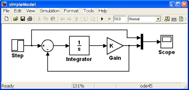
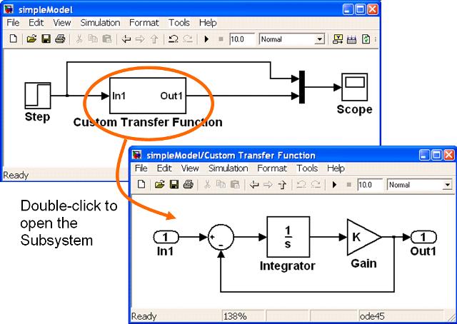
The model under consideration is shown in Figure 1. It is the same model developed in the Simulink Essentials - Building and Simulating Models tutorial, with a parameterized gain block as discussed in the Interfacing Simulink with MATLAB tutorial.
The blocks that need to be encapsulated into the subsystem need to be selected. The simplest way to do this is to rubber band a box around the blocks of interest. To achieve this depress the left mouse-button at a point in the model which will allow a rectangle to be drawn around all of the required blocks. Then (with the left mouse button still depressed) drag the mouse away from the original location. A block dashed box will be drawn on the screen, and get larger as the mouse is continued to be dragged. This is shown in Figure 2
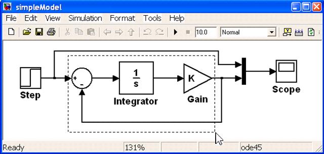
When the dashed box encircles all of the required blocks then release the left mouse button.
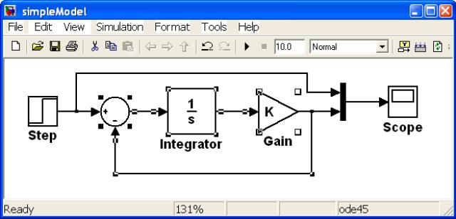
All of the blocks that were inside the dashed box will now be selected. Their selection is indicated by small black squares at the four corners of each selected block. Note that the lines connecting the blocks are also selected. This is indicated by the small black squares at each end of the line. This is shown in Figure 3
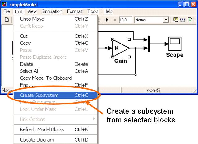
With the required blocks selected they can now be encapsulated into a subsystem using the Edit→Create Subsystem pull-down menu (as shown in Figure 4)
The result is a subsystem as shown in Figure 5. The subsystem is opened by double-clicking on it with the left mouse button.
The Mask Editor
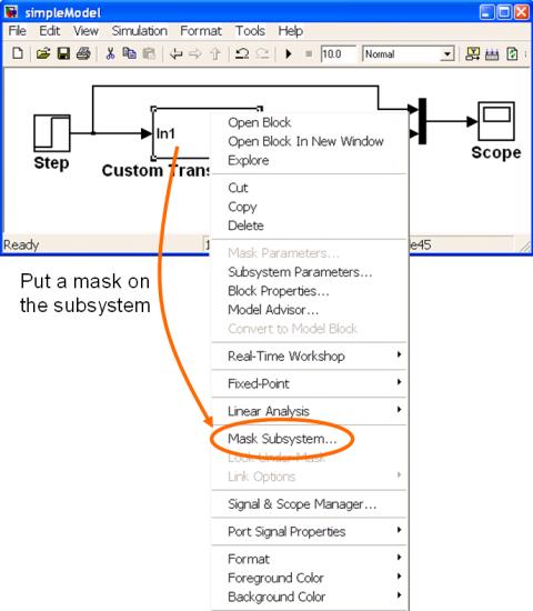
Once a subsystem has been created a mask can be put on top of it. This is shown in Figure 6 and involves right mouse clicking on the subsystem and selecting Mask Subsystem... from resulting Context Menu.
When Mask Subsystem... is selected the Mask Editor appears. This is a user interface for specifying what the mask should look like.

If at any time the Mask Editor is closed (either accidentally or deliberately) then it can be re-opened by right clicking on the subsystem/block and selecting the Edit Mask option.
The (top left hand corner of the) Mask Editor is shown in Figure 7. The Mask Editor has four tabs on it. Each tab is used to specify a different aspect of the mask and is discussed in the next four sections. (Note that this tutorial deals with the tabs in a different order to that in which they appear on the Mask Editor.)
- Specifying Block Help and Documentation.
- Specifying Block Parameters.
- Specifying a Block Icon.
- Specifying Initialization Code.
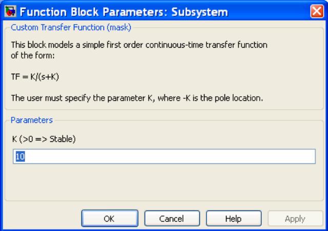
The final mask that is going to be created here is shown in Figure 8. Note that it has a similar format to the Properties dialog of all built-in blocks.
Specifying Block Help and Documentation
Three types of documentation are entered on the Documentation tab: the Mask Type; the Mask Description; and the Mask Help. Figure 9 shows how those three types of documentation correspond to what appears on the block’s dialog box.
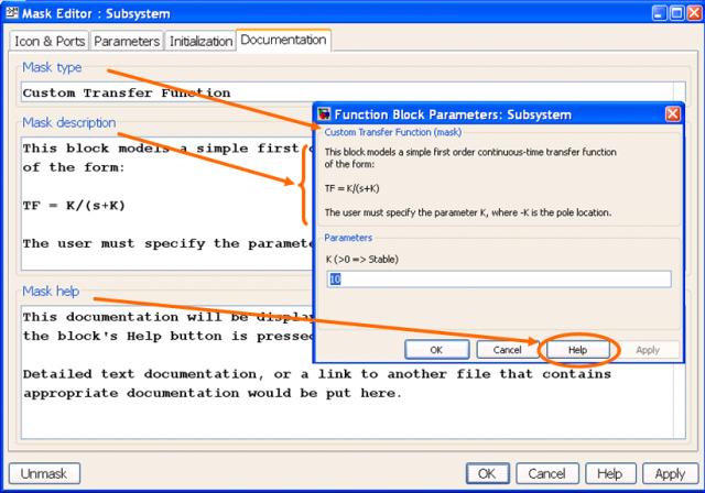
As can be seen in Figure 9, the Mask Type is a small, three or four word, comment that appears across the top of the block dialog. The Mask Description is a slightly longer description that briefly explains what the block does and what it needs to work correctly. This description appears as part of the block’s dialog when it is opened. And finally the Mask Help is more detailed documentation that will appear in the main MATLAB Help window when the block’s Help button is pressed. The Mask Help is often a link to a specifications document or HTML file.
Specifying Block Parameters
All parameters required by the blocks inside a Masked Subsystem must be passed to those blocks via (i.e through) the mask. This can be thought of as similar to the input arguments passed to a function or method in programming languages such as MATLAB, C and Java. This tab allows appropriate dialog boxes to be created to prompt the user for those required parameters.
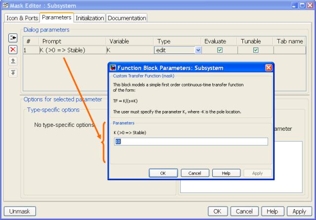
Each of the required parameters will appear on a separate line on the Parameters tab. Each line has several properties that can be set:
- Prompt: this is the text string that will describe a particular parameters.
- Variable: this must be the name of the variable as used by the blocks inside the Masked Subsystem.
- Type: this specifies what UI Widget should be used to enter the parameter. The edit box, check box and pop-up (selection) box options are the most commonly used.
- Evaluate: this indicates whether the values entered should be evaluated (in MATLAB) to obtain a numerical value for the parameter, or whether it should be taken as a literal value.
- Tunable: this indicates whether the parameter is tunable (i.e. can be changed) while a simulation is running, or whether the value is constant for the duration of a simulation.
- Tab name: the parameters dialog can be created with multiple tabs. This option specifies the name of the tab on which this particular parameter should appear.
There are also various other options available depending on the type of UI Widget selected and whether the parameter makes other parameters visible (or not) in the user interface. For instance, the developer may have a check-box that is checked force the user to enter additional information, hence the prompts related to that additional information would need to be displayed.
Figure 10 shows the Parameters Tab for the model under consideration. This specifies that there should be one parameter and gives: an appropriate prompt; that the parameter should be assigned to a variable called K; specifies that an edit box should be used to enter the parameter; that whatever is entered into the edit box should be evaluated in MATLAB to obtain the numeric value to use; that the parameter may be tuned during the simulation (if desired); and that there will only be one tab.
Specifying a Block Icon
The Icon & Ports tab allows an icon (i.e. an image, custom text, etc) to be placed on the subsystem, and for each input and output to be given a custom label. It is also where the developer specifies how the icon and/or text should behave when the block is rotated or flipped.
There are many different commands that can be used to specify the image or text to place on the subsystem. Examples of each of them is given in the region across the lower part of the tab (see Figure 11).
![]()
The different options for the icon are selectable down the left hand side of the tab. The options are:
- Block Frame: indicates whether the (usually black) rectangle around the block should be displayed or not.
- Transparency: indicates whether the icon should be see through (transparent) or not (opaque). With a transparent icon the names of the underlying Inport and Outport blocks can be seen through the icon.
- Units: specifies how the Icon Drawing Command should be scaled. (This is more important when an image or plot is used for the icon rather than text.)
- Icon Rotation: indicates whether the icon should rotate or flip if the block is rotated or flipped.
- Port Rotation: indicates how the input and output ports should be re-ordered as the block is flipped or rotated. (This is only important if a block has multiple inports or outports.)
Figure 11 shows the Icon & Ports Tab for the model under consideration. This specifies that the icon should simply be the text Custom TF; that the frame should be visible; that the inport and outport block names should not be seen through the icon; that the icon should be made to fit into the available block size; and that the icon should not rotate with the block. Since there is only one inport and one outport the Port Rotation option has no effect.
Specifying Initialization Code
The Initialization tab is a place to specify MATLAB code that must be executed when the model gets initialized at the start of a simulation.
For instance, there may be parameters used inside the Masked Subsystem that are not directly entered by the user but rather are calculated or derived from parameters that the user does enter. The calculation of the derived parameters should be performed by the code on the Initialization tab.
The Initialization tab for the model under consideration in this tutorial is shown in Figure 12, while Figure 13 gives a clearer view of the MATLAB code entered on the tab.
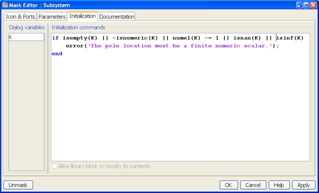
if isempty(K) || ~isnumeric(K) || numel(K) ~= 1 || isnan(K) || isinf(K)
    error('The pole location must be a finite numeric scalar.');
end
In this case the initialization code simply validates the data entered into the dialog box. The value entered must be finite, scalar, and numeric.
Using the Masked Block
Masked blocks are used in exactly the same way as any other Simulink block.
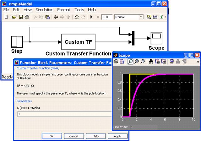
Figure 14 shows the final Custom Transfer Function block within the simpleModel. Double clicking on the block opens its parameters dialog box, and the dialog box has the same look and feel as all other Simulink blocks. The dialog explains what the block does and gives an edit box for the required transfer function parameter to be entered.
Once a parameter has been added the simulation may be run. The scope block in Figure 14 shows that the time response is as expected for a first order transfer function.
This tutorial has discussed topics related to creating Subsystems and Masked Subsystems. Other Simulink tutorials are available on the Software Tutorials page.